Search Results
86 results found with an empty search
- Ground Control - Principle 4
Collect Topo Check Shots Another important consideration when laying out your ground control is topo check shots. Check shots are just that - topo points we use to quality check the final 3D surface built from your drone flight. What's the difference between the two? Ground Control points locate your drone data in the correct place, check points are independent and what we use to verify accuracy. If we don't have check shots we will only know if your data is correct right on your GCP's, which it always is - because we told it to be. We suggest taking check shots more-or-less in between GCP's and in any critical areas. Try to mark them with about a 6" spot of paint, you don't need to number them. If you don't have any paint on hand, shoot them on a spot that will be recognizable from your drone flight, like the end of paint line on pavement, sawcut junction or a sidewalk corner. If places like that are not an option, just collect them where you can. Any check shot is better than no check shot. The general guidelines regarding where it's ok to place ground control applies to check points, too. The drone has to be able to see them from overhead and they need to be on spot with bare earth, a hard surface or mowed grass. If you are using your drone data for design and need to tie-in to an existing hard surface or drainage feature be sure to take check shots at each tie-in and flowline. We like to see about as many check shots as you have GCP's plus any critical areas and tie-ins. Of course, more is better to a point, but don’t get hung up on the exact number or feel like you need to capture 100 of them. In your field controller, when taking topo shots, just use a simple point descriptions. If they are an important spot like a tie-in or flowline, label them clearly. Otherwise, labeling them "check" is sufficient. Good point descriptions will make your field work much easier to understand in the office. They might even save a trip back to the field to collect more data. When it's time to export the points you can use the proprietary file type your GPS brand generates or a universal file type like CSV or TXT. However you export the data, be sure to select the Point #, Northing, Easting, Elevation and Description fields. One common mistake we see when contractors take check shots is they let the point of their rover sink into the dirt. This will give you a check shot a 0.1' or two lower than the actual surface. This will make the final 3D surface derived from your drone data appear to be high, when it is actually right on. If you have one, put a blunt topo shoe on the bottom of your rover pole. Here is the sewer plant we looked at in principle 2. Suggested topo check shot locations are shown with a yellow target labeled "CK". They are roughly between control with one on the berm between the lagoons. This road project has a few check shots on either side of the right-of-way and at two key intersections. Remember, check shots don't don't take a lot of planning. Just capture then as you travel between control points. Collecting them should add very little time to your field work, but give you a big piece of mind when it comes to proving your drone data is accurate. Next: Principle 5 - Measure GCP's with the same GPS system you are using for machine control Previous: Principle 3 - Set a few GCP's inside the site
- Ground Control - Principle 2
Surround the Site Surrounding the site with ground control is a simple, but often overlooked, step. Usually four to six GCP's will do it. They don't have to be exactly at the outer boundaries of the site, just close. If you drew a line between the outlying GCP's it should box in the site, or be close to it. The points that surround the site will do most of the heavy lifting in aligning your drone data with the engineer's site plan and your machine control model. If you are flying a long, narrow project like a roadway or levee place two points on each end of the flight plan and at least two or three spaced evenly between them. Add additional points as necessary to bend around a curve. On the right, the red bullseye's marked "GCP" show you suggested locations ground control locations for an odd shaped factory site. If we drew a line connecting the six GCP's out near the red boundary it would fully contain the site. Don't worry about the GCP's in the middle or the points marked "CK" just yet. We will talk about them in principle three and principle five. Here is a sewer plant project flown with the Quantum Flight Pack. It took just four GCP's to box in the site. On the left is a short, straight road project. There are two GCP's tying down each end of the project. These are very important to make sure the drone data does not twist or deviate from the correct orientation. Again, these four end points are the most important GCP's. If your flight requires multiple flight plans you will need to box in every flight with ground control, then overlap the flight plans over ground control in the sections that run together. This way, it will be easy to merge all of the flights into one continuous data set. Below is a section of road with two bends. Around the outside of the curve we placed extra control to box in the survey area. Again, play connect-the-dots between the outer GCP's and you will see that it encircles the project. This road is typical of how you would layout ground control for any levee, trail or roadway. It's the same concept for any linear project. Next: Principle 3 - Set a few GCP's inside the site Previous: Principle 1 - Location Matters
- Ground Control - Principle 3
Set a Few GCP's Inside the Site Once the site is boxed in with control it's time to place a couple more GCP's to dial in accuracy. These will help fine tune the photogrammetry process, too. Not something you need to worry about, unless you process your own data, but important nonetheless. To start, place a GCP on roughly the highest and lowest spots on your project. Don't worry about placing them on EXACTLY the highest and lowest points, just do what you can to get fairly close. Your highest and/or lowest points might be one of the boundary points from principle two, and that's ok. While your boundary points do much of their work by scaling in your drone data horizontally, these high/low points make sure you are scaled in to the full range of vertical elevations on your project. If your highest and lowest points are on the outer boundary, place a GCP close to the middle of the project. You should have a minimum of five GCP's for any flight. Why five? This blog post in our GPS Site Control series explains why, geometrically, five is the minimum necessary. Ideally, we like to see six to eight, or more for a larger site. For most construction sites (20 acres or less), six to eight control points will cover it. On a larger site place more control points evenly between the others. It's good to see a GCP every 500' to 800', more or less. You can stretch it out further on really big sites but keep in mind that your accuracy could start to drift between GCP's. In areas were elevations are critical place a GCP or two in or near those areas. That will guarantee the best accuracy possible for your flight where it counts the most. One more thing to keep in mind. It's good to have a little extra ground control in case you have a bad topo shot or one gets disturbed before you fly. Take a few extra minutes to make sure you have at least the minimum GCP's required in place and consider adding a couple more for "extra credit" On an active construction site you rarely get a second chance to collect the topo data you need. A couple "insurance" GCP's are well worth the time. Take a look at the sewer plant below. There are three GCP's inside the site boundary. One at the high point near the buildings in the north center of the site. Another is in a drainage basin to the south of it, the low point. There is a third on the middle of berm between the two lagoons. Any areas between bodies of water should have a GCP. The photogrammetry process does not work on water covered areas and we need to give it a little help with a GCP in that situation. The high point on the pre-construction flight for this golf course project was along the cart path, roughly in the middle of the project area. The low point was on the southwest corner, where one of the boundary GPC's was able to do double duty as the low point. The road section on the left has three control points between the ends of the project. It's best to alternate sides of the road and place a painted target in the middle of the road, if safely possible. Every 500' or so is enough in most situations, just make sure to hit the highs and lows and add more as you go around a curve. Consider placing extra GCP's in critical areas like near intersections or access roads. Next: Principle 4 - Collect Topo Check Shots Previous: Principle 2 - Surround the Site
- Intro to Ground Control for Drone Mapping
Quantum has broadcast loud and clear the best practices regarding site control for your GPS machine control systems. When expanding your tech repertoire into drone data, (we have heard the Quantum Flight Pack is good) it is just as important for you to understand how Ground Control Points (GCP) are utilized and why they are necessary when collecting drone data. Ground control is a target placed on the ground that can be seen in your drone photos. It is what ties your drone data to the "ground" and functions in much the same way as site control for your GPS system. We have broken the Ground Control process down into five simple principles you can apply to ANY drone data project and ANY drone system. Click on each one for a separate post with a detailed explanation. 1. Location matters 2. Surround the site 3. Set a few GCP's inside the site 4. Collect topo check shots 5. Measure GCP's with the same GPS system you are using for machine control The center of the GCP target is measured with the GPS system you are using for that project. We can see the targets in your drone photos, it's what we use to align your drone data with your machine control model, the project plans and any other survey work that has been done on the site. Without ground control, at the very best, your drone data will only be within a few feet of the correct location horizontally and dozens of feet off vertically. Nowhere near close enough to make it useful for much of anything when it comes to measuring your progress against the construction plans. Let's address the elephant in the GCP room --> There is a lot of buzz in the industry about PPK and RTK capable drones with very accurate photo geotags. They have their place and big potential, but you still can't beat the simplicity, low cost and reliability of standard ground control. You already have an expensive and highly accurate GPS base/rover system, may as well give it double duty in measuring ground control. Even with a PPK or RTK drone you should still have a few GCP's to guarantee your drone data will align with your machine control model. You rarely get a second chance to fly a constantly changing construction site. On the right, is a photo of a good ground control target. Note it has a clearly defined center, a matte finish and contrasting colors that show up well in drone photos. The basic design you see below is how most good quality GCP's are designed. Also, notice how this target is very low tech. Remember, you will use the GPS rover already set up on site to measure in the center of the target. If a dozer or truck runs over this target, its unfortunate, but you are only out the price of a good lunch. Not a few hundred $$$. It's ok to use ground paint in difficult to access or high traffic areas, but a good quality re-useable target is always best. If using ground paint, heavily paint the target and make it so the center will be easy to see from the air. Lightly painted or target colors that blend into the surface won't serve their purpose very well. Orange and blue seem to work well for most ground conditions.
- Ground Control - Principle 1
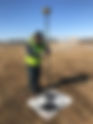
Location Matters In our mostly 2D life on the ground we usually don’t get too worried about what is overhead. When placing ground control, it is critical to look for overhead obstructions. If the drone can't see your GCP as it flies overhead, that GCP can't be used to make your data as accurate as it can be. As best as possible, make sure the drone will be able to capture photos of the GCP from all sides. If you need to place one near a tree, try to place the GCP at least the height of the tree away from it. Avoid placement under powerlines. If you can’t avoid powerlines entirely get out from directly under them. Move a few feet away from a fence line and don’t set a post or lathe right next to a target. Flatten or cut vegetation over about 1' tall right next to your GPC. Once you have done your best to clear overhead obstructions take a look at the ground. Place the target on a fairly flat area a few feet away from sudden grade changes. Instead of placing a target on an embankment, set it at the toe or top of the slope. Avoid placing a target in a parking space or intersection (we have seen more than one GCP with a F-150 or Camry on top). Don't set your target on the back of a curb or on a block wall. Now that you have a good location identified, all you have to do is place the target. Make sure the target is pinned or weighted down well enough to keep it in place for the duration of the flight. Then just place your rover in the center, level up and take the topo shot - just as shown in the photo below. If you are placing it on an existing survey nail or mark, the entire target needs to be flush with the surface and centered on the existing survey point. Give the point a simple description in your controller, like GCP1SW, for "ground control point 1 south west". A simple description like that will make your field work much easier to sort out for your data company or someone back at the office. It's nice to paint the GCP # next to the target, but that's not 100% necessary. It is mostly common sense here, but you would be surprised how many drone photos we receive where a target or two is obscured in most of the photos. One other thing, if someone is measuring in your GCP's while you are flying, remind them to avoid occupying a point as the drone passes over or near it! Next: Principle 2 - Surround the Site Previous: Intro to Drone Ground Control
- Ground Control - Principle 5
Measure GCP's With Same GPS System You Are Using For Machine Control ALWAYS, and only, measure in your ground control with a rover that is fully calibrated to the site control for your GPS system. Take the time to check your GPS system to make sure it is accurate that day. In the end, the only thing that matters is that your drone data lines up with the Engineer's design, your takeoff and your machine control model. If it does not, you will not be able to use the data for volume calculations or to measure production over the duration of you project. For this reason, all of your ground control and check shots should be measured in with the same base/rover GPS setup you are using for machine control. By using the same GPS system, calibrated to the correct site control, you will be guaranteed that your drone data will work in conjunction with any data collected on your site, past, present and future. To measure each ground control target or check shot, just place your rover in the center, level up and take the topo shot - just as shown in the photo to the left. Use a bi-pod if you have one. Your drone data can't be any more accurate than your ground control. A little extra effort here pays off here. Give the point a simple description in your controller, like GCP1SW, for "ground control point 1 south west". A simple description like that will make your field work much easier to sort out for your data company or someone back at the office. It's nice to paint the GCP # next to the target, but that's not 100% necessary. For topo check shots, label them "check" or "CK". Any check shots that are in an important spot like a flow line or tie-in just need to be labeled them clearly. When it's time to export the points you can use the proprietary file type your GPS brand uses or a universal file type like CSV or TXT. However you export the data be sure to select the Point #, Northing, Easting, Elevation and Description fields. That's it. Five simple to understand principles you can quickly apply to any drone mapping project. If you still need to make the jump and add a drone to your fleet, give the Quantum Flight Pack a look. 1. Location matters 2. Surround the site 3. Set a few GCP's inside the site 4. Collect topo check shots 5. Measure GCP's with the same GPS system you are using for machine control If you need to clear up any lingering questions regarding drone systems or ground control email us at sales@avqld.com or call 515-505-3510 ex: 702, we would be happy to hear from you.
- Site Control - Principle 4
Trust, but verify He never knew it, but Ronald Reagan's approach to dealing with the Soviets has a direct application to GPS machine control. This leads us to site control principle four. You hired the project Engineer to place your control, you surrounded the site with points and shot in more than five control points. What could go wrong now? A lot, if you don't use some independent checks to verify that your 3D model matches up to the real world. Here are a few things the surveyor can do while he is onsite to place your control. Usually, the cost to place a few more stakes is minimal the surveyor is onsite anyway. Consider it insurance. Set two or three building corners and mark cut/fill to finish floor elevation. This will allow you to check your site rotation and elevation at the building pad - one of the most important features on any project. If your project is, or incorporates, a new road, ask the surveyor to set a few centerline stakes with cut/fill to finish grade. Again, you can reference your 3D model and linework against it to make sure you are in the right place and reading cut/fills correctly. A couple stakes on the outer edge of your working area at an intersecting road are a good idea, too. Don't run all of your check stakes down the centerline, for reasons discussed in our site control principle 2 blog. Instruct the surveyor to place a benchmark on or near the center of the site that is easy to check. If the center of the site is not feasible, have them give you a benchmark that is easy to access and provides for good GPS reception. If the surveyor stakes utilities at the start of the project check your GPS system to their stakes. The elevations and locations should match your file. Use information about existing conditions from the plans to check your model to the real world. Take a look at the existing conditions plan sheet or grading plan. Look for existing manhole cover elevations, storm sewer inlet elevations, data at the site entrance(s), contour lines, property corners, etc. Any of this information can be helpful to back-check your GPS system to the actual site. If your project ties into an existing street, parking lot, driveway or hard surface, make sure your finish grade matches at the tie-in. There should be elevations called out at the tie-ins you can check against. Reading elevations at hard surface tie-ins might not be perfect due to freeze/thaw or subsurface moisture but should be close. If you have good GPS signal there, verify that your GPS matches the site vertical benchmark(s). Once you are happy with site control and are confident that it matches up to the site you can get to work. Operationally, there are checks you should perform regularly. Check your rover against a benchmark DAILY - before you start grading work. Use your rover to check the elevation across your dozer blade, motor grader, excavator, etc… every day. Even better, grade out a pass and make sure the dirt is to grade across the entire cutting edge. The finished dirt/rock elevation is what really matters in the end. Check your equipment against the benchmark stakes the surveyor placed for as long as they remain in place. Ensure your cut/fills match up against where you left off the day before. This is a quick way to know if something is off from day to day. Stake out to your site control points. When other trades like paving, foundation or even electrical contractors call for staking check your system to those stakes and make sure your system agrees with them. If you have measured in site control and are confident in your work, but your GPS system's reported residuals (errors) are high, talk to the surveyor. Finally, take good care of your - expensive - high tech equipment. Good maintenance can go a long way. We have quite a few clients running 10 year old GPS systems every day. Check your rover pole to make sure it is the correct length. You might have a worn or incorrect tip throwing your elevation off a little. If you measure in site control with a pole of the wrong length, your entire site will be shifted vertically. Consider this a reminder to double-check the pole length you have entered into your rover settings. Make sure the bullseye level bubble on your rover pole is not damaged or off. Is your software and firmware up to date? Some GPS suppliers will update it at no cost. Off season is the best time to do this. Do you need to adjust for cutting edge wear on your heavy equipment? The answer is probably yes. Is your heavy equipment "tight"? A motor grader with worn out linkages might measure in ok up by the job trailer but won't be on grade under load. Who would have thought greasing your equipment regularly would affect your GPS grade control systems accuracy? Lastly, does your GPS system and model pass the eyeball or gut test? Does it seem right when you are onsite? Is site drainage working as expected? While not perfect, a good gut check can go a long ways in making sure your GPS system is working correctly. If something just doesn't seem right, it probably isn't. Remember, you can always dust off that grade laser or dumpy level and use it to double-check your GPS system, too 4. Trust, but verify That's all there is to it. Four simple principles you can apply to any machine control project. 1. If at all possible, hire the project design engineer's surveyor to place your site control. 2. Surround the site with control points. 3. Calibrate to a minimum of five control points. 4. Trust, but verify. If you need to clear up any lingering questions regarding site control email us at sales@avqld.com or call 515-505-3510 ex: 702, we would be happy to hear from you. Rather watch a video? This companion video will walk you through all four principles and give you a few pointers on base station setup and control point placement. Start HERE if you would like to jump right to Principle 4. Quantum Land Design has built over 20,000 machine control models for earthmoving contractors across the US and Canada. Models, takeoffs and drone data are delivered within 3 business days and are compatible with Trimble, Topcon, Leica, Carlson, and many other systems.
- Site Control - Principle 3
Calibrate to a minimum of five control points. We touched on it in an earlier post, but the number of control points you calibrate to matters. Surrounding the site with control is important - but if three site control points encircle the project, is that enough? The answer is NO. You would never have guessed, but our site control discussion will take us to a bar stool for Principle 3. Have you ever noticed that a three legged stool never rocks, but a four legged stool does? If one leg of a three legged stool is a little short the top might be imperceptibly off level but the stool is still stable, it's not obvious your favorite bar stool has a problem. If you have a short leg on a four legged stool it will rock every time. Your GPS system's error checking works on much the same concept. Using only three control points might place your site in the world horizontally but vertically there is no way to check for errors. A fourth control point allows the system to compare the points against each other and find errors. A fifth point is important for redundancy and even better error checking. More than five points is best, but with five you can be confident that your site control has the project in the right place vertically and horizontally. Let's walk through each control point as you shoot them in to understand how each point helps to locate your project in the dirt. Keep in mind our analogy to using pins to place your site on a globe. When the first point is placed, it gets your site roughly where it needs to be but the system cannot rotate it correctly or place it vertically. Imagine placing that first "pin" in your project (the paper) on the globe. You could rotate the project in any direction. In the picture below you will see that site control point one (yellow triangle) has been measured in. The site is held at that point but it is not rotated correctly. The system cannot determine what is "north" on the virtual plans vs. the real world. The second point sets the rotation of the site - now it knows which way is north - but has no way to check if the site is rotated correctly. You will notice that once you have two control points shot in you can stake out to the others close enough to find them. Below you can see that two points have been shot in and the site is now correctly rotated. Notice that the entrance driveways on the right side of the plans now line up with the existing street. Point three gives the system the ability to error check site rotation and adjust it vertically. It still can't check control vertically (remember a 3 legged bar stool never rocks). After you have three good points measured in you will see that horizontally staking out to new points is really close, but vertically it will still be off. Shooting in the 4th control point will allow the system to error check the control points vertically. You will start seeing vertical errors in your control point readout. You now have the project fully "pinned" to the globe. In this picture, if you drew a line between each control point you will see that they box in the working area on this project, as described in our Principle 2 blog post. Measuring in the fifth point gives your GPS machine control equipment full redundancy to check all of the points against each other. If you think you have a bad point you can even turn them off one at a time to determine which one it is. Don't stop measuring in site control after you touch on the 5th hub. Each point you continue to shoot in will help improve the machine control system's accuracy and error checking. You may need more points to box in your site, too. It is best to shoot them all in at the beginning of a project even if you are not working in the outlying areas yet - those shiny new points might be disturbed by a lawnmower, farmer, homeowner (I have never met one that likes lathe in his yard) or even taken out by your own crew. 3. Calibrate to a minimum of five control points. Next: Principle 4 - Trust, but verify Previous: Principle 2 - Surround the site with control points Rather watch a video? This companion video will walk you through all four principles and give you a few pointers on base station setup and control point placement. Start HERE if you would like to jump right to Principle 3. Quantum Land Design has built over 20,000 machine control models for earthmoving contractors across the US and Canada. Models, takeoffs and drone data are delivered within 3 business days and are compatible with Trimble, Topcon, Leica, Carlson, and many other systems.
- Site Control - Principle 2
Surround the site with control points In our site control principle 1 article we discussed how every project is surveyed and designed on a virtual grid. Site control is what orients your GPS machine control system's 3D model and linework in the real world. It's what takes a virtual design and places it on the that corner lot or just outside the right of way. To orient your site, horizontally and vertically, in the real world it is important that your control points are well distributed. Let's imagine your project is drawn on a piece of paper and you have to place it on a globe. To get the paper - your project - to conform to the shape of the globe, you would need to pin down all of the edges. If you only pinned down one side or just three corners, the paper would drift away from the surface of the globe on the side opposite the pins. I may have oversimplified a little, but site control places your GPS machine control file in the real world in much the same way. To get your 3D model in the right place horizontally and vertically, you need to "pin" down the edges. A "pin" or two in the middle is good practice, particularly on large sites. See below for a couple illustrations showing good site control practices. Note that on every example if you drew a line between each of the control points (yellow triangles) on the outside edges, the working area (outlined in red) for the project would be entirely within the line. This project has three control points on the site and three a few hundred feet outside the site boundary. Control does not necessarily have to be on or right next to the project site. It might be down the block or across a stream. As long as you have good GPS signal and radio contact with your base station, it will work fine. It is more important to place control where you can get good GPS signal and it is not disturbed during construction than to have it right on the project site. In general, make sure your site control is placed away from trees, power lines, and tall structures. Here is an example of where control was placed on a round about project with several intersecting streets included in the project. Note that some of the control was placed a block from the project. This is the finished round about project. The perimeter control points were placed outside the working area, preserving them during the construction process. Road and highway projects can be tough to surround with control points but still must be fully encircled. They will require more control points for the area covered. Control must extend outside any adjacent streets or driveways that are included in the project. A good rule of thumb is to have control placed at least 250' on either side of the center line, or wider if grading for intersecting streets extends past 250'. On longer projects, make sure you have control points on both sides at least every half-mile; more if you have to work around a curve. The two pictures below are examples of good site control for a city street and interstate highway project. City Street Site Control Intestate Interchange Site Control One of the most common problems we see with control placement is when they are located on just one or two sides of a project. For example, say you are working on a subdivision project and are given three control points on the East property line and one 300' West of them - but the actual project extends 700' further West. Your GPS system does not show any errors when you finish measuring in control and your cut/fill is reading about as expected when you do some quick checks against the existing surface. Your crew finishes grading the site and the surveyor comes in to survey the as-builts for the project. The surveyor reports back that your work is about 0.3' high on the West end of the project but gets closer to grade as you get further East. There was no way to know, but remember that one control point 300' West of the East property line? It was 0.1' high. Your GPS system did not show any errors because it was the only point out of line with the rest. This is another example of how surrounding the site with control is so important. It allows the GPS system to check each point against the others for error. Had there been control points on the West side of the project your GPS system would have alerted you to the 0.1' error. You could have either not used the bad control point or known to have the surveyor check them before you started grading. This was an actual problem one of our new GPS clients had to deal with. We never asked what it cost to get the site rebuilt to spec. Another common site control placement blunder occurs when they are all placed in-line down the center of a road. Again, the GPS system did not display any control errors when you measured the points in. When you start checking cut/fills and elevation on the edge of the road or at intersections, the 3D model is high on one side and low on the other, but correct at the center line. The errors appear somewhat random as you move down the alignment. It seems like the model is bad. The problem is actually in the control placement. When control is placed in a straight or nearly straight line, the system cannot orient itself vertically on either side of control. The site model can tip one way or the other. Often, these errors are 0.5' or less, but we have seen errors of 3' high one side and 3' low on the other, just within the width of the road! Using control in the center of a road alignment is not a problem, just be sure anchor it with more points on both sides of the alignment. Remember to aim for at least 250' on both sides of the center line. The illustration below shows good control layout for a highway and a city street. The third big control error we see is when a contractor blindly uses the control points listed on a table in the plans. The control points (if any) listed on the plans were probably not intended for machine control. They are just what the surveyor used to orient his equipment to the site. Sometimes they will only list northings and eastings with one vertical benchmark elevation. The vertical benchmark could be from another point like a fire hydrant, power pole or manhole cover without a northing/easting location listed with it. They could reference a vague or unmarked location like a manhole cover or buried property corner. Usually the surveyor measured into them with a robotic total station and was not concerned with good GPS reception. How do you fix this issue? You don't. Best practice is to have the surveyor place new control points suitable for machine control around your site. They may use the existing control listed on the plans but will check it when they place the new points surrounding the site. It is not recommended to try and transfer a benchmark elevation or try to add your own control points. Surrounding your project with control is one of the best ways to ensure your job is located correctly and within grading tolerances. Principle 2: Surround the site with control points. Disclaimer: Every GPS manufacturer has their own recommendations for control placement and measurement. It is well worth the time to understand and implement their recommendations. Our suggestions above are great rules of thumb but your GPS supplier has the definitive answers on how to set up your system. Always consult them on very large projects like wind farms or long highway jobs. Next: Principle 3 - Calibrate to a minimum of five control points Previous: Principle 1 - If at all possible, hire the project design Engineer's surveyor to place your site control Rather watch a video? This companion video will walk you through all four principles and give you a few pointers on base station setup and control point placement. Start HERE if you would like to jump right to Principle 2. Quantum Land Design has built over 20,000 machine control models for earthmoving contractors across the US and Canada. Models, takeoffs and drone data are delivered within 3 business days and are compatible with Trimble, Topcon, Leica, Carlson, and many other systems.
- Site Control - Principle 1
If at all possible, hire the engineering firm that designed the project to place your site control. Your earth moving project site was surveyed and designed by the engineer on a virtual grid, really no different than the graphing paper you used back in school. Quantum's modelers take the engineer's plans and create a 3D model for your grading equipment that is referenced to the virtual grid originally laid out by the design engineer's surveyor. Site control is what allows your GPS equipment to know where you are on the engineer's design and places your machine control model in the correct place both horizontally and vertically. This leads us to our first principle of good site control. Why hire the design Engineer's surveyor, you ask? There may be someone that will do it cheaper, faster or you want to help out your brother-in-law's new surveying business. All of those are great reasons to hire someone else, but not good enough. The engineering firm that designed the site is the only one that has all of the information necessary to set your site control and the authority to figure out how to fix it if there is a bust. If getting it right the first time is not a good enough reason here are a few more (the list continues to grow) real world examples, courtesy of our clients to help you understand how important correctly placed site control is. On one of his first GPS jobs Contractor A took the low bid from a surveyor to place site control. He completed rough grading and excavated trench foundations, which were poured…only to find out his site control, and all of his work, was rotated 2.8 degrees from the correct orientation….. The design engineer's surveyor immediately found the issue as soon as he set up onsite. Contractor B thought he would save a buck and just use the control he found on one of the plan sheets - referenced to a couple manhole centers and a fire hydrant. What he missed was that vertical control was based on a railroad spike in an electric pole. When the design engineers surveyor staked the building it was 0.2' low. The elevations numbers on the manholes and hydrant were from old city plans. The $800 bucks Contractor B saved by setting his own control did not pan out He had to haul in thousands in rock to raise buildings and parking lots 0.2'. Contractor C worked on a large residential project that was in state plane control - or it seemed to be. Turns out the job had switched engineers a couple times. The original firm set up their site control and design in a "modified" state plane system. Somehow they started off a couple feet from true state plane control but went ahead and used that setup for design. The low bid surveyor hired to place the contractor's site control put it in the true state plane system. When Contractor C set up on site the machine control file and existing roads were not quite matching up. Contractor C lost 2 weeks of production by the time they figured out the issue and hired the design engineer to place control. Contractor's D through Z tried to use single point control on their engineered projects….. No need to share the stories here. It just never works right. Contractors A, B and C would have avoided costly delays and unplanned material expense had they chosen to hire the design engineer's surveyor. In every case the design and machine control model were correct and in the right location. Principle 1: If at all possible, hire the engineering firm that designed the project to place your site control. Next: Principle 2 - Surround the site with control points Previous: Get your 3D grading under control Rather watch a video? This companion video will walk you through all four principles and give you a few pointers on base station setup and control point placement. Start HERE if you would like to jump right to Principle 1. Quantum Land Design has built over 20,000 machine control models for earthmoving contractors across the US and Canada. Models, takeoffs and drone data are delivered within 3 business days and are compatible with Trimble, Topcon, Leica, Carlson, and many other systems.
- Get Your 3D Grading Under Control: 4 Site Control Principles Every GPS Contractor Needs to Know
Poor site control is the number one avoidable problem we see from contractors running GPS machine control. Not bad models or broken equipment. Site control, the first step on every single project. We've seen it cost contractors two weeks of production. We've seen it turn a correct machine control model for a balanced project into a mysterious site export. We've seen poured concrete footings that had to be redone because the control was rotated 2.8 degrees. Every one of those situations was avoidable. That's why we put together our site control series. If you're new to GPS machine control, or if you've been running it for years and have had some unexplained accuracy problems, this is worth your time. What Is GPS Site Control, and Why Does It Matter? Site control goes by a lot of names. Localization, site calibration, GPS control, benchmarks... Whatever your GPS supplier calls it, the concept is the same: it's what lines up your 3D machine control model with the real world. Your project was designed on a virtual grid. Our team takes the engineer's plans and builds a 3D surface model referenced to that same grid. Site control is what tells your GPS equipment where that model sits on the actual ground, both horizontally and vertically. Get it right, and grading starts clean. Get it wrong, and the whole job can drift in ways that are hard to diagnose until real damage is done. The 4 Principles of GPS Site Control Over years of working with contractors across the country, we've narrowed it down to four principles that apply to every project, every GPS brand, every site. 1. Use the Design Engineer's Surveyor When possible, hire the surveyor tied to the original design. They're the only ones who have all the information needed to set your control correctly and the authority to sort it out if something is wrong. There may be cheaper options. But the contractor who saves $1,200 by setting his own control from a plan sheet and then has to haul in 30 truck loads of rock to raise a parking lot 0.2' didn't actually save anything. We've seen that exact situation. 2. Surround the Site With Control Points Don't cluster control in the middle of the job. Place points around the perimeter so the entire working area is boxed in. Think of it like pinning a piece of paper to a globe. If you only pin one side, the other side drifts. Same thing happens with GPS control that's placed only on the east property line when the job extends 700 feet further west. The system won't flag an error. You'll just find out at as-built time that the west end is 0.3' high. Here's a full breakdown of how to surround the site correctly. 3. Calibrate to 5+ Points Three control points can place your site. Four lets the system start checking for errors. Five gives you full redundancy, vertically and horizontally. It's the same reason a three-legged stool never rocks but a four-legged one does. With only three legs, you can't tell if one is short. With four, the imbalance shows up immediately. Shoot all your control points at the start of the project, even for areas you won't work in yet. Those hubs won't survive contact with a lawnmower, a homeowner, or your own crew. Get them in early. Read the full breakdown on why five is the minimum. 4. Trust, But Verify Ronald Reagan said it about arms treaties. It applies just as well to machine control. Even with perfect control, daily checks against benchmarks and surveyor stakes are non-negotiable. Check your rover against a benchmark before you start grading. Verify grade matches where you left off the day before. When other trades come in for staking, check your system against their stakes. If something seems off, it probably is. You can always pull out a grade laser or dumpy level to cross-check your GPS. The full principle 4 post covers everything worth verifying. What Comes Next Each of the four principles has its own post in the series with field examples, illustrations, and the kind of detail you need to actually apply it on a job. If you're starting with GPS machine control for the first time, read them in order. If you're troubleshooting accuracy problems on an active project, Principle 1 and Principle 2 are often where the solution lies. Start with the original series intro if you want the full picture, or jump straight to any of the four principles above. Questions about site control or your machine control model? Call us at 515-505-3510 or email sales@avqld.com. FAQ: GPS Site Control for Machine Control What is GPS site control for machine control? Site control is the process of measuring in GPS reference points on your project site that align your GPS system and 3D machine control model with the real world. Without it, your model has no way to know where it sits on the ground horizontally or vertically. It is sometimes called localization, site calibration, or GPS calibration depending on your equipment brand. How many control points do I need for GPS machine control? A minimum of five. Three points can place your site, but give the system no way to check for vertical errors. A fourth allows error checking. A fifth adds redundancy so you can identify and remove a bad point if needed. More than five is better on large sites or long linear projects like roads. What happens if my GPS site control is set up wrong? Errors range from subtle grade discrepancies to work that has to be completely redone. We have seen sites rotated 2.8 degrees, parking lots graded 0.2' too low, and designs that appeared to tip or twist across the width of a road. In most cases the machine control model was correct. The control placement was the problem. Quantum Land Design has built over 20,000 machine control models for earthmoving contractors across the US and Canada. Models, takeoffs and drone data are delivered within 3 business days and are compatible with Trimble, Topcon, Leica, Carlson, and many other systems.
- How to Read an AGTEK Volume Report
AGTEK volume reports packs a lot of valuable information onto a single page, and if you haven't spent time with one before, it can be easy to misinterpret a value or pull the wrong number out and run with it. This post walks through a real report, the Hess Office project, so you know exactly what each section is telling you and how to use it in a bid. The Hess project may be simple, but the volume report for any project will hold the same information, just more of it. The first thing to remember is that all areas are in square feet (SF) and all volumes are in cubic yards (CY) Understand the Surfaces the Report is Comparing Before you look at a single number, you need to understand what surfaces AGTEK is comparing. Everything in the Volume Report section measures the difference between two things: Stripped Surface = Existing grade minus the stripping depth Subgrade Surface = Finish grade minus all sectional depths (pavement sections, building pad base, etc.) Cut means you're removing material to reach subgrade. Fill means you're adding material to build up to subgrade. These numbers do not represent your finish grade. They represent subgrade, which sits below all your sections like pavement or topsoil. Keep that straight and the rest of the report makes sense. The Hess Office Volume Report Here is the volume report as the contractor received it and a copy with annotations explaining each section and number. Feel free to download either for reference. Reading the Volume Report Section On the Hess Office report, the Volume Report breaks into two regions plus a total row. Building Pad covers just the building footprint: 14,991 sf total area, zero cut, 14,991 sf of fill, and a fill volume of 1,036 cubic yards. The Export/Import column shows -1,036. Negative means import. Positive means export. On this project the whole pad is going up from the stripped surface, so you're bringing material in. Grading covers everything outside the pad: parking, drives, slopes, everything else. Here you have 20,568 sf of cut and 27,568 sf of fill, with volumes of 1,085 CY cut and 1,248 CY fill. Export/Import is -163, meaning after using your cut to satisfy some of your fill, you still need to import 163 yards outside the building pad. Regions Total combines both: 1,085 CY cut, 2,284 CY fill, -1,199 CY Export/Import. That -1,199 is the number of import yards for the entire project. Negative is always import. If it were positive, you'd be hauling off surplus cut. One column worth paying attention to: Change per 0.1 ft. The Hess Office total is 253 CY per 0.1 foot. That tells you how much the import number shifts if the site grade moves up or down a tenth of a foot. Useful for value engineering, and a good conversation starter if grading costs are above budget. A note on compaction ratios (Comp/Ratio). Both columns show 1.00, meaning no shrink/swell adjustment is built in. Real material expands when you dig it and shrinks when you compact it. How much depends on your soil type and varies widely, sometimes even within a single project. Be sure to factor it in before you finalize the bid. We'll always use 1.0 but are happy to enter a shrink or swell %, just let us know your numbers when you request a takeoff. Stripping Quantities Below the Volume Report you'll find Stripping Qtys. On Hess Office, Site Strip covers 68,306 sf at a 0.500-foot depth for a total of 1,265 CY. The math: 68,313 sf slope area x 0.500 ft / 27 = 1,265 CY. You'll notice AGTEK shows both plane area and slope area. Volumes are always calculated from slope area because it accounts for the actual terrain rather than a flat footprint. Slope area will always be slightly larger than plane area. The Hess Office site is nearly flat, so the difference is minimal: 68,306 vs. 68,313. That 1,265 CY is topsoil coming off the whole site before any grading starts. It's a separate line item from your cut/fill. Price it separately as stripping volume IS NOT included in the volume report above. Sectional Quantities This is where most of the confusion happens. Sectional Qtys shows the material removed from finish grade on the plans to build the subgrade surface. Each pavement type, the building pad base, sidewalks, and topsoil respread areas all get their own line with their own area and depth. The sectional depths we use can be found on the plans. They'll include any material that must be removed to get to subgrade including rock and pavement. If depths are not noted on the plans we will use a typical depth and note that when we send the takeoff. If needed, we can adjust sectional depths after the takeoff is completed, just ask. Hess Office Sectional Quantities and Areas: Building Pad: 14,991 sf at 1.000 ft = 555 CY removed from finish floor to get to subgrade. That's the concrete slab and granular base. Concrete Pavement: 711 sf at 0.670 ft = 18 CY. HD Pavement (heavy duty): Two separate areas totaling 20,771 sf at 0.940 ft = 724 CY combined. LD Pavement (light duty): Four areas totaling 9,952 sf at 0.770 ft = 284 CY combined. Respread: Seven green space areas totaling 19,503 sf at 0.500 ft = 364 CY. That's topsoil redistributed back onto landscaped areas. It doesn't leave the site. Walk (sidewalks): 2,378 sf at 0.670 ft = 59 CY. The Sectional Total at the bottom is 2,004 CY. You'll rarely use that number directly. It combines pavement base, pavement, building slab, topsoil respread, and sidewalks into one figure, which isn't useful for pricing. Pull the individual line items and price them by material type. Remember the sectional depth CY totals are the complete volume removed from finish grade to build the subgrade surface. To find the volume for rock base under any paving area you'll need to take the slope area * the rock base depth. The AGTEK volume report does not provide tonnage. You'll need to do the CY to tonnage conversion on your own. Putting the Numbers to Work For the Hess Office, here are they key numbers you'll need to build your bid: Import to reach subgrade: 1,199 CY Topsoil strip: 1,265 CY Building pad area: 14,991 SF HD pavement slope area: 20,784 SF LD pavement slope area: 9,965 SF Concrete pavement section slope area: 732 SF Sidewalk section slope area: 2,380 SF Topsoil respread: 364 CY The report gives you the quantiles and slope areas you need to figure an accurate bid. Frequently Asked Questions What is an AGTEK volume report? An AGTEK volume report is an earthwork quantity summary generated by AGTEK takeoff software. It calculates cut and fill volumes between two surfaces — typically the stripped existing grade and the subgrade then breaks those quantities down by region, stripping, and sectional areas. Estimators use it to bid earthmoving work on commercial and civil construction projects. What is the difference between cut and fill in an earthwork takeoff? Cut is material removed from the site to reach subgrade elevation. Fill is material added to build up to subgrade. On a given project you'll have areas of each, and the difference between your total cut and total fill determines whether you'll be exporting surplus material or importing what you're short. AGTEK reports both the area in square feet and the volume in cubic yards for each. What does the export/import number mean in an AGTEK report? Export/Import is the net difference between cut and fill volumes at subgrade. A negative number means you need to import material; your fill exceeds what you're cutting on site. A positive number means you have surplus cut to haul off or stock onsite. On the Hess Office project, the Regions Total shows -1,199 CY, meaning 1,199 cubic yards of fill needs to come in from off site. What are sectional quantities in an earthwork takeoff? Sectional quantities represent material removed from finish grade to build the subgrade surface. This covers pavement and rock base sections, building pad concrete and granular base, topsoil respread on green areas, and sidewalk sections. Each section type has its own area and depth, and AGTEK calculates the volume of the full sectional area using: slope area x depth / 27. These quantities and areas are NOT included in the main cut/fill volumes and are typically priced at different unit costs in the bid. Requesting a Takeoff from Quantum Send the full set of plans to takeoffs@quantumlanddesign.com or call us directly at 515-505-3510 ext. 710 to discuss. PDF's of the plans is all we need quote and complete your takeoff. You can learn more about Quantum's takeoff services and download project examples at our Takeoffs/Volumes page. Quantum Land Design has built over 20,000 machine control models for earthmoving contractors across the US and Canada. Models, takeoffs and drone data are delivered within 3 business days and are compatible with Trimble, Topcon, Leica, Carlson, and many other systems.