Search Results
80 results found with an empty search
- Quantum Flight Pack - Phantom 4 Pro and Mavic 2 Pro Training
Here are all of our DJI Phantom 4 Pro and Mavic 2 Pro training videos. Both drones fly using the free Ground Station Pro software on an iPad. Bookmark this site and subscribe to our YouTube channel , we're always working on new content to help you make the most of your construction technology. Topographic Survey Flight Planning Camera Settings for Topographic Flights Low Light Camera Settings for Topographic Flights Reuse a Flight Plan
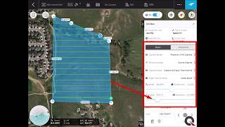
- DJI Mavic 3E Flight Planning - Quantum Flight Pack
We just posted a new Quantum Flight Pack video. Learn how to plan a topographic mapping mission for a construction site in DJI's Pilot 2 software. This flight plan is optimized for the new Mavic 3E. A GPS machine control model and drone flight are all you need to get started in monitoring your project with the lastet construction technology. Want to learn more about how to set up ground control and use the data collected with your Quantum Flight Pack (or any drone system)? Click here to head over to our Education page.
- ConExpo 2023 Invitation
We’d like to invite you to join Quantum Land Design at ConExpo 2023.
- PAC-MAN!
When Caterpillar's Edwards Demonstration and Learning Center has a challenging project, they know who to call. This time, they tasked our own Ryan Murguia with designing a PAC-MAN game board, in the dirt. From getting the proportions right in real life, to earthwork calculations then on to Cat GRADE ready GPS machine control models Ryan had them covered. Watch the Cat Trials #9 video below:
- Cat Trial 11: Hot Wheels
Carpet racing, construction and/or farming are where most of us get our start in the industry. Caterpillar decided to take the kids from the carpet to the construction site with real Hot Wheels, real Caterpillar equipment and a real Quantum machine control model in Cat Trial 11: Hot Wheels. Quantum's Ryan Murguia worked with the team at Caterpillar's Edwards Demonstration and Learning Center to bring Hot Wheels to life. Ryan built custom machine control models for the entire course from the huge jump to the banked turns. Cat's Demonstrator/Instructors loaded Quantum's model and built the race track with the latest Next Gen Cat Grade technology. We are biased, but can't think there is a more fun way to get kids interested in STEM careers. Watch below.
- SANY America and Leica Geosystems Partnership
Interested in adding Leica Geosystems machine control to your SANY excavator and/or motor grader? Through their Joint Technology Program, SANY America dealers have access to Leica machine control systems, including lease and purchase agreements. Installation and support are handled by Leica's dealer network. The Technology Access Program offers Sany customers the opportunity to operate Leica equipped at the SANY Digs demo area near Atlanta, GA. Talk to your SANY dealer to schedule a demo. Click on the picture below for further details.
- Quantum's YouTube Pro Series Continues to Grow
It's important to us that our clients are successful with their machine control systems. Keep an eye on the growing Pro Series on Quantum's YouTube channel. We regularly add new content to help you get the most our of your construction technology. Subscribe to let us know you appreciate the content and would like to see it keep coming. Here is our latest video. It might feature a Komatsu dozer, but the wisdom applies to any color or equipment.
- Quantum Flight Pack - Flight Planning Video
Supplement your GPS machine control system with Quantum's Flight Pack drone kit. Subscribe to our YouTube Channel to learn how to put the latest technology to use in your business. In this video, follow an easy step-by-step tutorial of DJI's Ground Station Pro automated flight app. Ground Station Pro is pre-installed on every Quantum Flight Pack system.
- Structurally Correct
Have you thought about using your GPS machine control system for structural excavation? It might not be common place, yet, but we have more clients requesting structural excavation models every year. Depending on your needs and equipment, there are a couple ways we can set up the files for you. The first is simple. We put the 2D linework in your GPS file for stakeout or to double check your manual measurements. Here is a picture of what it might look like: You can use your rover to stakeout to the linework and check elevations vs. the project plans. It is similar to how you would use the linework to stakeout a utility like a watermain. It sure beats staking the whole project or pulling a tape measure from batter boards. While 2D is great there is still room for improvement. The most progressive contractors are moving to 3D modeling for their structural excavations, just like they use a 3D surface model to grade the rest of the project. Quantum's experts take the location and depth information from the Engineer's design to build a 3D model of the structural plans. That 3D model then guides your excavator to dig in the correct location and depth required by the plans, no more, no less. You can use your rover to stakeout locations and depth, too. The 3D model can show all of the elements of foundation excavation like stoops, continuous footings, pad footings, thickened slabs and even foundation drainage. Your excavator operator can dig with confidence knowing they are doing the work right the first time. There is no need for a grade checker to continuously check grade with a laser, or even slower, a tape measure. The 3D model can be set up to match the over-dig required by the concrete contractor or to match your machine's bucket width. If your excavation requires shoring or safe back slopes we can build the model to take that into account. On some projects, part of the foundation may require over excavation due to poor soil conditions. Just let our experts know what you need when you request the model. Often, the biggest pay off comes when it is time to place concrete. Small over excavations are easy to make without the continuous grade control provided by a GPS excavator and 3D model. Let's make the math easy. Assume we have a small 300' long by 3' wide x 3' deep trench footing. The entire trench will be filled with concrete. It should take 100cy of concrete. If it is over excavated by only 3" it will take an extra 8.3 yards of concrete to pour the trench footing - that is an entire extra mixer truck - over $1,000 in concrete. Keep in mind you will have an extra dump truck load of dirt to export or waste onsite, too. Seemingly small structural excavation errors can quickly add up to big bucks. A word from the wise…. DO NOT blindly use linework from the civil plans to stake out or excavate for any structure. You need to verify that the linework matches the structural plans. Often times, the building outlines or even bridge abutments in the civil CAD file are not kept up to date with the latest structural engineering changes. For this reason, Quantum's experts only build structural excavation models from the structural plans, the "S" sheets in most plan sets. It might seem complicated at first, but once you have your first 3D structural excavation job under your belt you will never go back. To take the leap Email or call us at 515-505-3510.
- American Flat Track
Machine control models aren't just for commercial projects. Quantum's experts improved a problem jump and fixed track drainage issues for the Peoria Motorcycle Club - making one of the oldest tracks in the American Flat Track circuit even better. American Flat Track news detailed how the latest construction tech made short work out of a big problem. Here is the link --> https://www.americanflattrack.com/news/view/cat-rescue-peoria-again
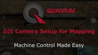
- DJI Drone Camera Settings for Mapping and Survey
Quality pictures are required to get the best from your drone data. Here is a quick video showing you how to set up the camera on your DJI drone for surveying and mapping missions. Don't have a drone yet? Check out the Quantum Flight Pack. We have another video that will help you set up your mission plans here. Have questions? Just email me or call at 515-505-3510 ex 702.
- ConExpo-Con-Agg Trip Giveaway
Here is your chance to walk through the gates at Conexpo-Con/Agg for FREE in 2023. All you have to do for a chance at show tickets and $500 bucks is toss your name in the virtual hat. Click on the picture below to try your luck.